RadiMation Application Note 141
How to create and apply a cable correction
This RadiMation® application note explains how to create a cable correction and how to use it in RadiMation®.
Cable corrections can be applied for several reasons, for example:
- To compensate cable losses in emission measurements
- To compensate attenuators in a conducted immunity calibration setup
- To compensate the cable loss from a coupler to a power meter in an immunity test
By specifying the actual correction for the cable loss, RadiMation® will be showing the correct measurement values.
The procedure to determine and select a cable correction, consist of 3 steps:
- Create a calibration file.
- Create a Cable device driver and apply the correction file.
- Add the cable to the test equipment.
Create a calibration file
There are two methods to create a correction file:
Measure attenuation or gain
It is possible to use the attenuation gain measurement to automatically create a correction and measure the cable or attenuator with a signal generator and a power meter or spectrum analyser.
this is described here: Attenuation / Gain System Calibration
Create a correction manually
To create a correction file manually, first create a new correction file, using the menu:
The Insert row button can be used to add additional rows. The cells in the frequency and correction columns can be used to specify the correct frequencies and the corresponding attenuation values.
The correction file can be saved to disk, by selecting from the menu:
It is also possible to paste data from for example Microsoft Excel with the Paste button ![]() .
Make sure the data on the clipboard is specified in present in MHz and attenuation values expressed in dB.
This feature is particularly used when correction values are supplied in a digital calibration certificate or is measured with other software.
.
Make sure the data on the clipboard is specified in present in MHz and attenuation values expressed in dB.
This feature is particularly used when correction values are supplied in a digital calibration certificate or is measured with other software.
Create a cable device driver
A new cable device driver can be created by selecting from the menu:
- Choose Configurable cable and click New.
- Enter an appropiate description for the cable or attenuator.
- The Device driver settings window, is shown. The fields in this window can be specified to provide any additional information regarding the cable.
- In the Correction files section, the previously saved correction file can be selected at Cable Loss.
- Click OK to close the window.
Add the cable to the test equipment
The final step is to update the test equipment to use the corrected cable.
This can be configured in the test equipment, which can be done by selecting from the menu:
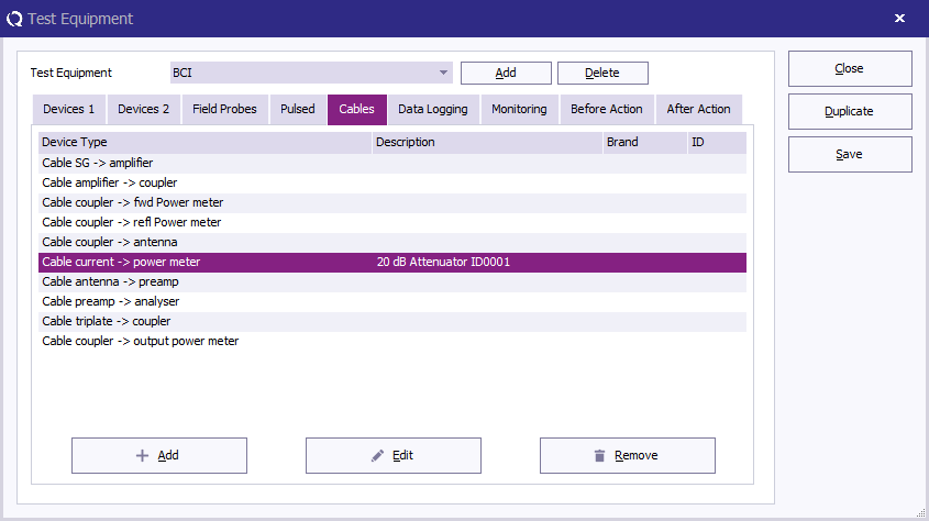
Selecting the cable can be done by:
- Select the applicable test equipment at the Test equipment dropdown box. (Or create a new test equipment using the Add button)
- Select the Cables tab.
- Click the Add button, select the applicable cable path in which the cable is used, and select the previously created cable device driver.
- Save the changes and Close the dialog.
If multiple cables or attenuator are used in a specific cable path (for example in the Cable current -> power meter path), then multiple cable device drivers can be added to that same cable path. RadiMation® will internally add all the separated cable losses into a single overall cable loss before it is used in the actual test.
Conclusion
Using the steps in this application note it is possible to measure a cable loss, and configure it in RadiMation®. After these steps RadiMation® will be able to perform and present more accurate absolute measurement values.


