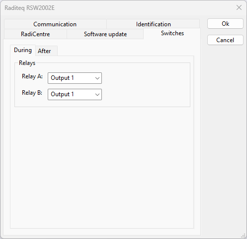
The Switches tab allows to configure the actual state of the relay on the switch card.
 During and After During and After
|
There are two switch configurations. These two configurations are during and after the test. The settings on the During tab are send to the switch matrix just before the test is started. The settings on the After tab are send to the switch matrix after the test has ended.
This allows that the relay switch settings can be completely different during and after the test. A possible situation is that the input of the analyser needs to be disconnected from the antenna, after the test has ended, to be sure that high voltage levels are damaging the analyser input. Another possible scenario is that the high power amplifier is switched to a dummy load, after the test has ended, to be sure there is no RF power in the anechoic chamber.
| Relay A
|
The output state that should be activated for Relay A on the switch card. It is also possible to not switch at all with the option Do not change
|
| Relay B
|
The output state that should be activated for Relay B on the switch card. It is also possible to not switch at all with the option Do not change
|
|
