Uncategorized files
Showing below up to 500 results in range #1 to #500.
View (previous 500 | next 500) (20 | 50 | 100 | 250 | 500)
 113-Global.png 1,021 × 339; 25 KB
 113 - Global-Local.png 946 × 331; 22 KB
 127-ColumnChooser.png 465 × 346; 12 KB
 127-EmissionTable.png 1,603 × 818; 91 KB
 14-CorrectionCurve.png 1,454 × 747; 55 KB
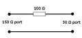 150 ohm to 50 ohm adapter.jpg 391 × 183; 6 KB
 1st screen.png 499 × 387; 13 KB
 2nd screen.png 499 × 387; 21 KB
 3rdScreen.png 499 × 387; 9 KB
 4thScreen.png 499 × 387; 10 KB
 5thScreen.png 499 × 387; 9 KB
 6thScreen.png 499 × 387; 14 KB
 ADChannelInputConfiguration.png 574 × 490; 19 KB
 AM Modulated Signal Amplitude Conservation.png 639 × 451; 4 KB
 AM Modulated Signal No Conservation.png 639 × 451; 3 KB
 AN101 Continuous Measure Manual Mode.png 295 × 364; 9 KB
 AN101 Frequency Range.png 1,018 × 280; 29 KB
 AN101 Graph Angle overview.png 635 × 90; 6 KB
 AN101 No Peaks No Final Detectors.png 346 × 284; 8 KB
 AN101 Number Of Sweeps.png 273 × 90; 4 KB
 AN101 Optimize Angle Settings TSF.png 481 × 340; 20 KB
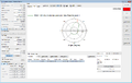
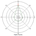 AN101 Polar Plot Angle.png 485 × 491; 13 KB
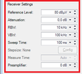 AN101 Receiver Settings.png 272 × 245; 7 KB
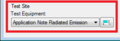 AN101 Test-Site.png 270 × 93; 4 KB
 AN101 Test Equipment.png 775 × 581; 31 KB
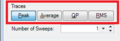 AN101 Traces.png 270 × 93; 5 KB
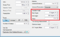 AN101 Turntable Angle.png 528 × 324; 28 KB
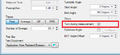 AN101 Turntable Angle Turn during measurement.png 525 × 242; 14 KB
 AN103 AntennaDiagramFinalPolarPlotGraph.png 1,439 × 914; 93 KB
 AN103 AntennaDiagramFrequencyGraph.png 1,439 × 915; 80 KB
 AN103 AntennaDiagramPolarPlotGraph.png 1,439 × 914; 88 KB
 AN103 AntennaDiagramTSF.png 1,035 × 710; 55 KB
 AN103 AntennaDiagramTSFMultipleFrequencies.png 1,035 × 710; 66 KB
 AaroniaSpectran Driver communication.png 510 × 465; 8 KB
 AbsorbingClampOverload.png 890 × 458; 26 KB
 AddCableTestEquipment.png 845 × 474; 20 KB
 AddColumns.png 776 × 375; 15 KB
 AddDriver2.png 1,664 × 820; 84 KB
 AddFieldProbes.png 707 × 400; 11 KB
 AddProbesToTestSite.png 1,680 × 1,050; 88 KB
 AddedProbestoInputs.png 1,210 × 1,006; 86 KB
 AdvancedAntennaTowerPanel.png 498 × 483; 11 KB
 AdvanedSwitchMatrix.png 512 × 463; 12 KB
 AgilentU2000ASettings.png 497 × 464; 9 KB
 Agilent N9038A Input Tab.png 608 × 401; 12 KB
 Agilent N9038A Settings Tab.png 608 × 401; 12 KB
 Amplifier.png 699 × 714; 17 KB
 AmplifierControlWindow.png 469 × 139; 4 KB
 AmplifierControlWindowManager.png 471 × 126; 5 KB
 AmplifierControlWindowOpening.png 911 × 272; 15 KB
 Amplifier control window.png 303 × 294; 5 KB
 Antenna correction factor.png 732 × 765; 28 KB
 Attachments.png 1,022 × 793; 23 KB
 AttenuationGainSystemCalibration.png 960 × 318; 19 KB
 Attenuation EUT Calibration Configuration Window.png 700 × 465; 23 KB
 Attenuation EUT Calibration Result Window.png 748 × 603; 32 KB
 Attenuation System Calibration Configuration Window.png 668 × 478; 21 KB
 AuthorizationTab.png 513 × 436; 6 KB
 AutoPolling.png 1,013 × 553; 42 KB
 AutoResize.png 839 × 761; 26 KB
 AxisSpecificCorrections.png 774 × 372; 16 KB
 BackupDeviceDrivers.png 956 × 470; 34 KB
 Black Dongle.JPG 500 × 142; 25 KB
 Black Dongle Sleutel Hanger.JPG 500 × 277; 40 KB
 CANoeExample.png 1,267 × 1,016; 211 KB
 CANoeSystemVariables.png 685 × 735; 45 KB
 CANoe AD Convertor signal selector.png 439 × 330; 9 KB
 CANoe CAPL messages.png 1,267 × 1,017; 72 KB
 CANoe EUT Monitoring Input Setup.png 604 × 539; 22 KB
 CANoe Simulation setup.png 1,267 × 1,017; 66 KB
 CE101 Test Configuration.png 1,049 × 725; 50 KB
 CE101 Test Result.png 1,286 × 860; 78 KB
 CE101 Test layout.png 923 × 576; 13 KB
 CE102 Test Configuration.png 994 × 725; 51 KB
 CE102 Test Result.png 1,282 × 910; 102 KB
 CE102 Test layout.png 976 × 484; 14 KB
 CS109 Test Configuration.png 1,017 × 693; 39 KB
 CS109 Test Result.png 1,277 × 850; 66 KB
 CS109 Test Setup.png 1,019 × 477; 32 KB
 CS109 Test level.png 1,011 × 507; 30 KB
 CS109 Test level configuration.png 610 × 280; 11 KB
 CS114 Calibration.png 934 × 479; 32 KB
 CS114 Calibration band 1.png 677 × 566; 35 KB
 CS114 Current Testlevel Configuration.png 755 × 420; 22 KB
 CS114 Current limit.png 610 × 280; 10 KB
 CS114 EUT Testing.png 1,126 × 498; 35 KB
 CS114 Equipment 1.png 845 × 474; 21 KB
 CS114 Equipment 2.png 845 × 474; 21 KB
 CS114 Equipment 3.png 845 × 474; 23 KB
 CS114 Modulation settings.png 690 × 370; 14 KB
 CS114 Test Result.png 1,283 × 850; 82 KB
 CS114 Test Setup.png 1,017 × 693; 40 KB
 CS114 Test level.png 1,123 × 557; 41 KB
 CS114 Verification.png 942 × 498; 30 KB
 CS114 Verification Result.png 1,283 × 850; 79 KB
 CS114 Verification Setup.png 1,017 × 693; 41 KB
 CableDeviceDriver.png 730 × 721; 22 KB
 CalibrationExpireDatabase.png 946 × 536; 9 KB
 Calibration jig factor 0 dB for 50 Ohm system.png 366 × 210; 9 KB
 Calibration jig factor 150 Ohm for 150 Ohm system.png 366 × 199; 8 KB
 Calibration jig factor 50 Ohm for 50 Ohm system.png 366 × 199; 8 KB
 Calibration jig factor 9.5 dB for 150 Ohm system.png 365 × 210; 7 KB
 Calibration probe selection.png 708 × 562; 30 KB
 Canalyzer.png 1,247 × 1,010; 103 KB
 Capture lan During.png 600 × 353; 25 KB
 Capture lan save window.png 563 × 601; 28 KB
 CarrierOffOn.png 1,233 × 823; 52 KB
 CarrierStepDown.png 1,233 × 823; 52 KB
 CarrierStepUp.png 1,233 × 823; 52 KB
 Ceyear technologies 1466H-V back.jpg 1,988 × 698; 454 KB
 Ceyear technologies 1466H-V front.jpg 1,987 × 700; 450 KB
 Change password.png 859 × 422; 18 KB
 ChangingUsernamePassword.png 1,355 × 1,017; 95 KB
 Check.png 713 × 681; 52 KB
 ChoosingUnitsForCorrectionColumn.png 770 × 529; 21 KB
 ColumnsCorrectionFile.png 819 × 525; 23 KB
 ColumnsUnits.png 1,454 × 747; 62 KB
 Communication.png 524 × 496; 21 KB
 CommunicationTab.png 512 × 435; 7 KB
 Communication Settings.png 510 × 548; 7 KB
 Communicationswitch.png 510 × 465; 14 KB
 Communicationswitch2.png 510 × 465; 15 KB
 Communicationswitch3.png 510 × 465; 15 KB
 Compression.png 668 × 572; 31 KB
 ConfDvdr.png 605 × 31; 2 KB
 ConfDvdrNetworkFolder.png 194 × 46; 1 KB
 Config-Config.png 584 × 241; 34 KB
 ConfigList.png 1,063 × 678; 103 KB
 ConfigTestLevelVoltage.png 611 × 366; 12 KB
 Config default address information.png 1,024 × 250; 11 KB
 Config engineers.png 1,024 × 250; 11 KB
 Config test equipment.png 1,024 × 250; 11 KB
 ConfigurableAntennaTowerTab.png 543 × 826; 14 KB
 ConfigurableCalibrationJig.png 377 × 215; 6 KB
 Configurable Modulation Source Carrier tab.png 502 × 315; 7 KB
 Configurable Modulation Source Init and Check tab.png 502 × 315; 6 KB
 Configurable Modulation Source Waveform tab.png 502 × 323; 6 KB
 Configurable Signal Generator Configuration Window.png 502 × 624; 11 KB
 Configurable Turn Table Configuration Window.png 510 × 548; 10 KB
 Configurable XYZ Positioner.PNG 510 × 581; 13 KB
 Configurable signal generator.png 1,049 × 585; 42 KB
 Configurable signal generator edit.png 731 × 722; 32 KB
 Configurable switch matrix configuration window custom2.png 570 × 493; 21 KB
 Configurable switch matrix configuration window custom3.png 570 × 493; 19 KB
 Configurable switch matrix configuration window custom4.png 570 × 493; 20 KB
 Configuration.png 69 × 63; 1 KB
 ConfigurationFolders.png 944 × 536; 30 KB
 Configuration Directories Manager.png 946 × 537; 32 KB
 Configuration Enhanced Status Window Empty.png 1,003 × 540; 22 KB
 Configuration Enhanced Status Window Font.png 433 × 351; 13 KB
 Configuration language2.png 1,049 × 585; 14 KB
 Configuration pull down menu.png 910 × 250; 10 KB
 Configuration units change2.png 1,049 × 585; 34 KB
 Configuration units test selection.png 1,050 × 587; 25 KB
 ConfigureAnalyzerAsPowerMeter.png 515 × 492; 23 KB
 ConfigureLimitLines.png 1,017 × 690; 33 KB
 ConfigureLimitLinesAfterTest.png 1,308 × 885; 66 KB
 ConfigureTestLevelCurrent.png 609 × 281; 9 KB
 ConfigureTestLevelEField.png 728 × 487; 17 KB
 ConfigureTestLevelVoltage.png 611 × 377; 12 KB
 ConfigureTestLevelVoltageSubstitution.png 663 × 420; 18 KB
 Configure emco 5390.png 497 × 462; 11 KB
 Configure milmega with configurable amplifier.png 505 × 500; 22 KB
 Connect power sensor to calibration setup.png 343 × 126; 3 KB
 Connect power sensor to power reference.png 339 × 126; 4 KB
 CorrectionFile.png 1,031 × 589; 21 KB
 CorrectionFileExcel.png 423 × 672; 28 KB
 CorrectionUnits.png 1,454 × 747; 49 KB
 Correction file correction columns.png 1,454 × 747; 41 KB
 CouplerSettingsPanel.png 498 × 243; 5 KB
 CouplingMode.png 563 × 485; 8 KB
 CreateAndSelectAmplifierDeviceDriver.png 1,241 × 746; 43 KB
 CreateCorrection.png 405 × 195; 10 KB
 CurrentProbeMeasurement.png 896 × 445; 33 KB
 CurrentSensorCalibrationEUTCalibration.png 758 × 338; 13 KB
 CurrentSensorCalibrationSystemCalibration.png 769 × 214; 11 KB
 Current sensor Transfer impedance Prove.PNG 726 × 328; 3 KB
 Current sensor Transfer impedance Ref measurement.PNG 616 × 254; 6 KB
 Current sensor Transfer impedance example.png 703 × 318; 3 KB
 Current sensor Transfer impedance final measurement.PNG 579 × 281; 6 KB
 DARE!! Measurements ADC Configuration.png 564 × 176; 9 KB
 Database customer.png 1,050 × 588; 22 KB
 Database device driver.png 1,051 × 587; 17 KB
 Database device driver config.png 1,049 × 585; 22 KB
 Delete test equipment.png 841 × 514; 25 KB
 Detect.png 524 × 496; 35 KB
 DetectorCaptionLocation.png 1,009 × 155; 9 KB
 DetectorMapPanel.png 510 × 433; 9 KB
 DeviceConfigurationExpireDate.png 699 × 714; 15 KB
 DeviceDriverAntennaTowerAdvanced.png 497 × 462; 6 KB
 DeviceDriverIdentification.png 543 × 193; 3 KB
 DeviceDriverLeCroyChannelSelectionTab.png 497 × 233; 5 KB
 DeviceDriverOptionTab.png 510 × 201; 3 KB
 DeviceDriverRadiCentreDeviceSoftwareUpdateTab.png 510 × 228; 5 KB
 DeviceDriverRadiCentreTab.png 510 × 268; 7 KB
 DeviceDriverRadiSense2000Tab.png 510 × 305; 6 KB
 DeviceDriverRadiSenseTab.png 510 × 490; 10 KB
 DeviceDriverRadiSenseUserCalibrationTab.png 510 × 330; 10 KB
 DeviceDriverReferenceClockTab.png 510 × 174; 3 KB
 DeviceDriverReferenceTab.png 510 × 319; 8 KB
 DeviceDriverResolutionTab.png 510 × 149; 3 KB
 DeviceDriverSoftwareUpdateTab.png 510 × 237; 5 KB
 DeviceDriverUnitSelection.png 510 × 262; 7 KB
 DeviceManagerOtherDevicesRadiPower.png 668 × 769; 33 KB
 DeviceManagerShowHiddenDevices.png 668 × 279; 19 KB
 DeviceManagerUSBDevicePropertiesDetailsInstancePath.png 400 × 455; 11 KB
 DeviceManagerUninstallDeviceAndDelete.png 666 × 768; 42 KB
 DeviceManagerUninstallSerialPortDeviceAndDelete.png 666 × 767; 53 KB
 DeviceSpecificSettingsRadiMationFreeWindow.png 327 × 625; 19 KB
 Device configure.png 1,048 × 250; 10 KB
 Device driver add.png 1,049 × 585; 22 KB
 Device driver configuration.png 1,049 × 585; 40 KB
 Device driver configuration2.png 1,049 × 585; 41 KB
 Device driver edit.png 1,049 × 585; 22 KB
 Device driver remove.png 1,049 × 585; 22 KB
 Device driver remove2.png 1,049 × 585; 28 KB
 Device driver settings.png 731 × 722; 21 KB
 Device driver settings window amplifier.png 703 × 664; 14 KB
 Device driver type.png 1,050 × 587; 24 KB
 Device manager.png 795 × 579; 97 KB
 Devicedrivers.png 1,003 × 543; 51 KB
 DevicesPowermeter.png 714 × 861; 29 KB
 Disable password.png 910 × 543; 30 KB
 Dongle-keyhanger.jpg 4,000 × 3,000; 2.27 MB
 Download-button.png 118 × 29; 1 KB
 Download.png 489 × 105; 8 KB
 DriversExeComponentsSelection.png 499 × 387; 16 KB
 DriversExeFinished.png 499 × 387; 41 KB
 DriversExeInstalling.png 499 × 387; 12 KB
 DriversExeRestartPC.png 499 × 387; 43 KB
 DriversExeUpdatingMicrosoftRuntime.png 481 × 298; 12 KB
 DriversExeVersionSelection.png 499 × 387; 13 KB
 ERROR REPORT FILE ZIP.png 1,499 × 817; 101 KB
- ESAI and ESBI Manual.pdfESAI and ESBI Manual.pdf File missing
 EUT-Measurement.png 788 × 558; 24 KB
 EUTColumnChooser.png 989 × 655; 26 KB
 EUT RG Template.png 976 × 647; 23 KB
 EUT TEST LIST.png 973 × 639; 24 KB
 EUT main info.png 956 × 667; 48 KB
 EUT new test environmental data.png 994 × 626; 39 KB
 EUT test data example.png 1,375 × 976; 82 KB
 Enable password.png 910 × 542; 28 KB
 EnabledAmplifierControlWindowInAmplifierDeviceDriver.png 731 × 722; 27 KB
 EngineerNoPasswordSet.png 464 × 251; 15 KB
 Engineer add engineer.png 531 × 280; 6 KB
 Engineer delete engineer.png 531 × 280; 6 KB
 Engineer delete engineer confirm.png 531 × 280; 9 KB
 Engineer edit engineer.png 531 × 280; 6 KB
 Engineers admin.png 531 × 280; 5 KB
 EnhancedWindowWithTest.png 1,295 × 528; 25 KB
 Equipment Under Test EUT Information Add Cable.png 985 × 667; 28 KB
 Equipment Under Test EUT Information Edit Cable.png 984 × 667; 35 KB
 Equipment Under Test EUT Information Remove Cable.png 985 × 667; 31 KB
 Equipment under test example.png 956 × 667; 47 KB
 ErrorPopupWindow.png 736 × 240; 8 KB
 Error report screen.png 548 × 537; 18 KB
 Events problem report generator.PNG 1,162 × 811; 56 KB
- Example.docExample.doc File missing
 Explorer.png 1,380 × 579; 73 KB
 Facebook-icon.jpg 26 × 26; 606 bytes
 FieldProbePanel.png 555 × 490; 12 KB
 Field sensor Advanced settings Axis Configuration.png 510 × 490; 10 KB
 File New Limit Line.png 910 × 250; 11 KB
 File Open Limit Line.png 910 × 250; 11 KB
 File Save Limit Line.png 910 × 250; 11 KB
 File new correction file.png 1,048 × 250; 12 KB
 File new eut.png 910 × 250; 11 KB
 File open correction.png 1,048 × 250; 11 KB
 File open eut.png 910 × 250; 12 KB
 File save correction.png 1,048 × 250; 10 KB
 Formula.png 332 × 29; 1 KB
 FrankoniaWebInterface.png 633 × 459; 195 KB
 FromToClipboard.png 674 × 298; 14 KB
 HV-LVAttenuationGainEUTCalibration.png 973 × 345; 19 KB
 HV-LVAttenuationGainEUTCalibrationResult.png 661 × 511; 25 KB
 HV-LVAttenuationGainEUTCalibrationResultGraph.png 1,013 × 808; 67 KB
 HV-LVCouplingAttenuationEUTCalibrationTSF.png 668 × 437; 23 KB
 HV-LVCouplingAttenuationSystemCalibrationTSF.png 667 × 379; 18 KB
 HarmonicTSF.png 664 × 551; 24 KB
 HarmonicsSpectrumAnalyserAndAntennasEquipment.png 1,222 × 344; 23 KB
 HarmonicsSpectrumAnalyserAndPowermeterEquipment.png 1,022 × 350; 20 KB
 HarmonicsSpectrumAnalyserEquipment.png 784 × 391; 19 KB
 Harmonics configure test.png 622 × 474; 23 KB
 Harmonics test results.PNG 990 × 524; 31 KB
 ImmunityPeakTable.png 1,305 × 895; 56 KB
 Inderface.can.png 679 × 248; 13 KB
 InjectionDevicePanel.png 376 × 218; 4 KB
 Inputs.png 1,204 × 969; 56 KB
 InsertNode.png 209 × 220; 5 KB
 InsterNodeCircle.png 241 × 183; 5 KB
 Interlock-driver-switches.png 510 × 500; 15 KB
 Interlock-radicentre-back.jpg 800 × 600; 132 KB
 Interlock-select-testsite.png 739 × 550; 30 KB
 Interlock schema.png 800 × 382; 19 KB
 IsotropicCorrections.png 771 × 373; 16 KB
 Keysight GPIB 488 Compatible mode.png 861 × 593; 20 KB
 Keysight Technologies 53220A Device Driver Settings.png 542 × 351; 21 KB
 Keysight Technologies N9048B back.jpg 4,701 × 1,933; 1.38 MB
 Keysight Technologies N9048B front.jpg 5,139 × 2,129; 1.69 MB
 LSProbe1Settings.png 762 × 484; 11 KB
 LSProbeTCPServerCI.PNG 979 × 512; 9 KB
 Limit Line Default.png 968 × 560; 25 KB
 MIL-STD-462-N1.pdf ; 239 KB
- MIL-STD-462-N2.pdf ; 93 KB
- MIL-STD-462-N3.pdf ; 5.38 MB
- MIL-STD-462-N4.pdf ; 133 KB
- MIL-STD-462-N5.pdf ; 1.18 MB
- MIL-STD-462-N6.pdf ; 385 KB
- MIL-STD-462.pdf ; 2.96 MB
 MSTeamsOpenChat.png 603 × 215; 56 KB
 MSTeamsOpenLink.png 756 × 353; 39 KB
 MSTeamsSelectScreen.png 318 × 159; 8 KB
 MSTeamsStartScreenShare.png 319 × 158; 8 KB
 MagneticFieldClosedLoopTestlevelConfiguration.png 618 × 320; 12 KB
 MagneticFieldOnForwardPowerSubstitutionTestlevelConfiguration.png 674 × 443; 22 KB
 MagneticFieldOnPowerSystemCalibration.png 1,398 × 429; 38 KB
 MagneticFieldOnPowerTestConnections.png 1,187 × 422; 29 KB
 MagneticFieldShuntResistor.png 331 × 380; 14 KB
 MagneticFieldSubstitutionTestlevelConfiguration.png 674 × 443; 22 KB
 MagneticFieldSystemCalibration.png 1,102 × 376; 37 KB
 MagneticFieldTestConnections.png 917 × 382; 26 KB
 ManualReportMenu.png 948 × 686; 37 KB
 Maturo NCD back.jpg 2,513 × 820; 1.16 MB
 Maturo NCD front.jpg 2,513 × 759; 1.09 MB
 MeasureLoop.png 771 × 530; 13 KB
 MeasurementSetup.png 468 × 206; 29 KB
 Measuring.png 1,218 × 1,003; 100 KB
 MeasuringTable.png 1,216 × 1,003; 108 KB
 MetraHitBd232.zip ; 48 KB
 Microrad-devicedriver-configuration.png 1,205 × 830; 138 KB
 Microrad-share-menu.png 789 × 648; 100 KB
 Microrad-share-running.png 789 × 648; 81 KB
 Microsoft Visual C++ 2015 Redistributable.PNG 1,133 × 220; 53 KB
 MillMegaTCPIP.png 637 × 581; 24 KB
 MkMesstechnikOnScreenDisplayCommunication.png 924 × 503; 8 KB
 MkMesstechnikOnScreenDisplayDevice.png 924 × 503; 8 KB
 MkMesstechnikOnScreenDisplaySettings.png 924 × 503; 30 KB
 Modular overview.png 428 × 503; 30 KB
 MonitoringWindow.png 972 × 653; 23 KB
 Monitoring input channel setup calculation.png 594 × 510; 32 KB
 Monitoring input channel setup calculation old style.png 594 × 510; 29 KB
 Monitoring input channel setup range.png 594 × 510; 32 KB
 MultiBandRampConfiguration.png 1,113 × 457; 18 KB
 MultibandFieldDistribution.png 992 × 765; 57 KB
- Multiband Report Template.doc ; 112 KB
 NIUpdateServiceCollapsed.png 700 × 550; 17 KB
 NIUpdateServiceSelected.png 700 × 550; 28 KB
 NIUpdateServiceUpdate.png 699 × 550; 25 KB
 NRVD Settings.png 510 × 470; 10 KB
 NRX-GPIB.jpg 868 × 359; 32 KB
 NSG4060TSConfig.PNG 1,014 × 692; 39 KB
 NSG4060TestSite.PNG 1,008 × 635; 23 KB
 NSG4060VoltageTestLevelConfig.PNG 610 × 372; 11 KB
 NSG4070.png 1,532 × 799; 58 KB
 NetworkAnalyserCalibration.png 757 × 492; 37 KB
 NetworkSetup.png 933 × 527; 27 KB
 NewCorrection.png 1,007 × 505; 21 KB
 New signal generators.png 1,049 × 585; 41 KB
 New test equipment.png 841 × 514; 25 KB
 OPCDriversExeStartPage.png 499 × 387; 14 KB
 Open Limit Line.png 999 × 561; 22 KB
 Open correction.png 999 × 561; 42 KB
 Open eut.png 999 × 561; 45 KB
 PHASE-A setup.png 1,137 × 621; 32 KB
 PMM EP600 Settings.png 510 × 490; 6 KB
 PM Modulated Signal.png 639 × 451; 2 KB
 PecosDetermineIPAdress.png 1,353 × 1,018; 124 KB
 PecosSelectLicense.png 276 × 54; 4 KB
 PecosStreamCaptions.png 1,260 × 459; 46 KB
 Persistable object not registered.png 900 × 303; 100 KB
 Phase B setup.png 1,170 × 663; 31 KB
 Pilot interface device driver configuration.png 526 × 309; 10 KB
 PolarizerPanel.png 498 × 482; 5 KB
 PolarizerSettingsPanel.png 496 × 483; 5 KB
 PowerCompressie.png 757 × 485; 15 KB
 PowerMeterConfigurationExample.png 510 × 283; 9 KB
 PowerMeterPanel.png 510 × 473; 9 KB
 Powermeterconnected.png 1,019 × 558; 38 KB
 PrgramNodeconfig1.png 692 × 255; 12 KB
 Probe TEM Verification.jpg 4,608 × 3,456; 3.33 MB
 ProgramFiles.png 671 × 43; 2 KB
 ProgrammingCorrectionTable.png 728 × 718; 51 KB
 Pulsed Imm EUTMonitoring.JPG 1,680 × 1,010; 189 KB
 Purple dongle.jpg 544 × 177; 19 KB
- QuantumChangeTileCapabilities.ppt ; 2.85 MB
 RE-ANTENNA-SPURIOUS-AND-HARMONIC-OUTPUT.png 1,105 × 805; 64 KB
 RE101 Loop configuration.png 735 × 788; 29 KB
 RE101 Test configuration.png 1,100 × 798; 66 KB
 RE101 Test layout.png 1,037 × 479; 20 KB
 RE101 Test measure peak.png 1,357 × 944; 96 KB
 RE102 Test Configuration.png 1,100 × 801; 66 KB
 RE102 Test Result.png 1,453 × 976; 88 KB
 RE102 Test layout.png 900 × 483; 15 KB
 RI-FIXED-POWER-0dBm-SignalPower.png 994 × 767; 41 KB
 RS103 Limits.png 1,007 × 505; 23 KB
 RS103 Modulation settings.png 690 × 370; 14 KB
 RS103 Test configuration.png 994 × 766; 50 KB
 RS103 Test level.png 730 × 390; 16 KB
 RS103 Test result.png 1,268 × 948; 78 KB
 RS103 Test setup.png 980 × 496; 16 KB
 RSAnalyzerPreset1.png 389 × 201; 101 KB
 RSAnalyzerPreset10.jpg 799 × 599; 117 KB
 RSAnalyzerPreset11.jpg 1,113 × 834; 279 KB
 RSAnalyzerPreset2.png 522 × 662; 51 KB
 RSAnalyzerPreset3.png 389 × 201; 101 KB
 RSAnalyzerPreset4.jpg 627 × 470; 88 KB
 RSAnalyzerPreset5.jpg 706 × 530; 119 KB
 RSAnalyzerPreset6.png 64 × 42; 4 KB
 RSAnalyzerPreset7.jpg 666 × 499; 91 KB
 RSAnalyzerPreset8.png 64 × 42; 4 KB
 RSAnalyzerPreset9.jpg 753 × 565; 117 KB
 RSUPP400PossibleConfiguration.png 945 × 555; 135 KB
 RSUPP400PossibleNumericDisplay.png 861 × 206; 42 KB
 RSUPP400RetrievableFieldsFromNumericDisplay.png 839 × 397; 121 KB
 RSW2002E Switch settings.png 497 × 482; 10 KB
 RadiAmpChannelSelectionPanel.png 497 × 483; 6 KB
 RadiGenOutputSettingsPanel.png 498 × 484; 6 KB
 RadiLogSaveAs.png 1,232 × 583; 53 KB
 RadiMationDeviceDriverSettings.png 730 × 722; 21 KB
- RadiMationInterface.zip ; 1,011 bytes
 RadiMationPathSettings.png 946 × 536; 23 KB
 RadiMationSuccesfullDeviceDriverCheck.png 304 × 126; 3 KB
 RadiatedImmunityMilStdCalibrationConfiguration.png 673 × 496; 23 KB
 RadiatedImmunityMilStdCalibrationOnForwardPowerConfiguration.png 672 × 496; 23 KB
 RadiatedImmunityMultibandMagneticClosedLoopConfiguration.png 994 × 766; 47 KB
 RadiatedImmunityMultibandMagneticSubstitutionConfiguration.png 995 × 766; 47 KB
 Radiated Emission Multi Band Band A Band B.png 285 × 154; 2 KB
 Radiated Immunity Substitution Configuration Window.png 835 × 735; 40 KB
 Radiated Immunity UFA Calculated Power.png 1,171 × 618; 65 KB
 Radicentre Switch Matrix configuration.png 353 × 560; 8 KB
 RadimationFree.png 210 × 46; 2 KB
 ReceiveAntennaCorrection.png 735 × 788; 29 KB
 ReferenceClockSettingsPanel.png 498 × 484; 6 KB
 RemoteVISADeviceConfig.png 495 × 482; 11 KB
 RenameProbe.png 540 × 118; 5 KB
 Report2.png 542 × 472; 23 KB
 ReportErrorWindow.png 662 × 541; 19 KB
 ReportGeneratorDocumentLocation1.png 941 × 473; 16 KB
 ReportGeneratorDocumentLocation2.png 1,005 × 716; 35 KB
 ReportGeneratorOutputLogo.png 959 × 713; 35 KB
 Report Generator Settings Window Advanced Options.png 956 × 667; 41 KB
 Report generator.png 48 × 48; 2 KB
 ResetPanel.png 498 × 484; 6 KB
 Result Enhanced Status Window enabled font color red horizontal.png 1,055 × 294; 8 KB
 ResultingCorrectionFile.png 501 × 504; 14 KB
 RiSubstitution.png 668 × 632; 46 KB
 Rohde & Schwarz FPC1000 back.jpg 4,913 × 2,233; 1.97 MB
 Rohde & Schwarz FPC1000 front.jpg 5,037 × 2,357; 2.59 MB
 Rohde & Schwarz FSP 30 back.jpg 2,516 × 1,389; 1.71 MB
 Rohde & Schwarz FSP 30 front.jpg 2,530 × 1,389; 1.77 MB
 Rohde & Schwarz UPP400 back.jpg 4,741 × 939; 693 KB
 Rohde & Schwarz UPP400 front.jpg 4,452 × 886; 609 KB
- Rssi usb driver.zip ; 14 KB
- Rssiup vxipnp 1 6.zip ; 2.96 MB
 S21InsertLossExample.png 222 × 149; 30 KB
- SCPI-99.pdf ; 4.17 MB
 SafeNet USB SuperPro-UltraPro device driver properties.png 400 × 455; 13 KB
 Save Limit line As.png 999 × 562; 22 KB
 Save correction as.png 999 × 562; 42 KB
 Save eut as.png 999 × 562; 45 KB
 ScatteringParameters.png 546 × 222; 22 KB
 ScatteringParametersMultiplePorts.png 300 × 209; 55 KB
 Schwarzbeck BBV 9745 front.jpg 4,221 × 1,652; 1.14 MB
 Scope connection alias test.png 412 × 259; 4 KB
 Screenshot configurable amplifier configuration window.png 505 × 500; 21 KB
 Screenshot configurable switch matrix configuration window.png 570 × 493; 20 KB
 SelectExport.png 261 × 224; 3 KB
 SelectExportGraph.png 1,015 × 631; 27 KB
 SelectNewConfdvdr.png 800 × 130; 7 KB
 SelectProbe.png 496 × 449; 12 KB
 SelectTraxeforAxis.png 1,683 × 1,011; 105 KB
 Select Filter Wireshark.png 540 × 460; 42 KB
 SendTo.png 587 × 483; 17 KB
 Sentinel Setup Example.png 514 × 394; 28 KB
 Sentinel System Driver installed.png 984 × 349; 30 KB
 SeperateDrivers.png 989 × 537; 22 KB
 Sequence overview.png 792 × 316; 15 KB
 SetAxisProbe.png 510 × 490; 14 KB
 SetPrimaryBoard.PNG 866 × 685; 59 KB
 Setup cdn bci calibration.gif 605 × 275; 8 KB
- Siemens Efficient 5950 Router configuratie.pdfSiemens Efficient 5950 Router configuratie.pdf File missing
- Sma manual complete.pdfSma manual complete.pdf File missing
 SpectranUSBTCPBridge started.png 567 × 337; 10 KB
- SpectrumAnalysysis.pdf ; 3.08 MB
 Stanalonepowermeter.png 1,015 × 557; 35 KB
 SwitchAmp1.png 539 × 117; 4 KB
 SwitchAmp2.png 538 × 113; 5 KB
 SwitchMatrix.png 946 × 570; 28 KB
 SwitchMatrixAmp.png 699 × 714; 22 KB


