Uncategorized files
Showing below up to 250 results in range #1 to #250.
View (previous 250 | next 250) (20 | 50 | 100 | 250 | 500)
 113-Global.png 1,021 × 339; 25 KB
 113 - Global-Local.png 946 × 331; 22 KB
 127-ColumnChooser.png 465 × 346; 12 KB
 127-EmissionTable.png 1,603 × 818; 91 KB
 14-CorrectionCurve.png 1,454 × 747; 55 KB
 150 ohm to 50 ohm adapter.jpg 391 × 183; 6 KB
 1st screen.png 499 × 387; 13 KB
 2nd screen.png 499 × 387; 21 KB
 3rdScreen.png 499 × 387; 9 KB
 4thScreen.png 499 × 387; 10 KB
 5thScreen.png 499 × 387; 9 KB
 6thScreen.png 499 × 387; 14 KB
 ADChannelInputConfiguration.png 574 × 490; 19 KB
 AM Modulated Signal Amplitude Conservation.png 639 × 451; 4 KB
 AM Modulated Signal No Conservation.png 639 × 451; 3 KB
 AN101 Continuous Measure Manual Mode.png 295 × 364; 9 KB
 AN101 Frequency Range.png 1,018 × 280; 29 KB
 AN101 Graph Angle overview.png 635 × 90; 6 KB
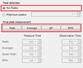 AN101 No Peaks No Final Detectors.png 346 × 284; 8 KB
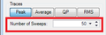 AN101 Number Of Sweeps.png 273 × 90; 4 KB
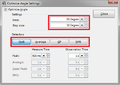 AN101 Optimize Angle Settings TSF.png 481 × 340; 20 KB
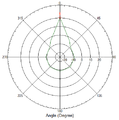 AN101 Polar Plot Angle.png 485 × 491; 13 KB
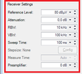 AN101 Receiver Settings.png 272 × 245; 7 KB
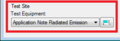 AN101 Test-Site.png 270 × 93; 4 KB
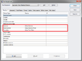 AN101 Test Equipment.png 775 × 581; 31 KB
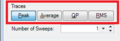 AN101 Traces.png 270 × 93; 5 KB
 AN101 Turntable Angle.png 528 × 324; 28 KB
 AN101 Turntable Angle Turn during measurement.png 525 × 242; 14 KB
 AN103 AntennaDiagramFinalPolarPlotGraph.png 1,439 × 914; 93 KB
 AN103 AntennaDiagramFrequencyGraph.png 1,439 × 915; 80 KB
 AN103 AntennaDiagramPolarPlotGraph.png 1,439 × 914; 88 KB
 AN103 AntennaDiagramTSF.png 1,035 × 710; 55 KB
 AN103 AntennaDiagramTSFMultipleFrequencies.png 1,035 × 710; 66 KB
 AaroniaSpectran Driver communication.png 510 × 465; 8 KB
 AbsorbingClampOverload.png 890 × 458; 26 KB
 AddCableTestEquipment.png 845 × 474; 20 KB
 AddColumns.png 776 × 375; 15 KB
 AddDriver2.png 1,664 × 820; 84 KB
 AddFieldProbes.png 707 × 400; 11 KB
 AddProbesToTestSite.png 1,680 × 1,050; 88 KB
 AddedProbestoInputs.png 1,210 × 1,006; 86 KB
 AdvancedAntennaTowerPanel.png 498 × 483; 11 KB
 AdvanedSwitchMatrix.png 512 × 463; 12 KB
 AgilentU2000ASettings.png 497 × 464; 9 KB
 Agilent N9038A Input Tab.png 608 × 401; 12 KB
 Agilent N9038A Settings Tab.png 608 × 401; 12 KB
 Amplifier.png 699 × 714; 17 KB
 AmplifierControlWindow.png 469 × 139; 4 KB
 AmplifierControlWindowManager.png 471 × 126; 5 KB
 AmplifierControlWindowOpening.png 911 × 272; 15 KB
 Amplifier control window.png 303 × 294; 5 KB
 Antenna correction factor.png 732 × 765; 28 KB
 Attachments.png 1,022 × 793; 23 KB
 AttenuationGainSystemCalibration.png 960 × 318; 19 KB
 Attenuation EUT Calibration Configuration Window.png 700 × 465; 23 KB
 Attenuation EUT Calibration Result Window.png 748 × 603; 32 KB
 Attenuation System Calibration Configuration Window.png 668 × 478; 21 KB
 AuthorizationTab.png 513 × 436; 6 KB
 AutoPolling.png 1,013 × 553; 42 KB
 AutoResize.png 839 × 761; 26 KB
 AxisSpecificCorrections.png 774 × 372; 16 KB
 BackupDeviceDrivers.png 956 × 470; 34 KB
 Black Dongle.JPG 500 × 142; 25 KB
 Black Dongle Sleutel Hanger.JPG 500 × 277; 40 KB
 CANoeExample.png 1,267 × 1,016; 211 KB
 CANoeSystemVariables.png 685 × 735; 45 KB
 CANoe AD Convertor signal selector.png 439 × 330; 9 KB
 CANoe CAPL messages.png 1,267 × 1,017; 72 KB
 CANoe EUT Monitoring Input Setup.png 604 × 539; 22 KB
 CANoe Simulation setup.png 1,267 × 1,017; 66 KB
 CE101 Test Configuration.png 1,049 × 725; 50 KB
 CE101 Test Result.png 1,286 × 860; 78 KB
 CE101 Test layout.png 923 × 576; 13 KB
 CE102 Test Configuration.png 994 × 725; 51 KB
 CE102 Test Result.png 1,282 × 910; 102 KB
 CE102 Test layout.png 976 × 484; 14 KB
 CS109 Test Configuration.png 1,017 × 693; 39 KB
 CS109 Test Result.png 1,277 × 850; 66 KB
 CS109 Test Setup.png 1,019 × 477; 32 KB
 CS109 Test level.png 1,011 × 507; 30 KB
 CS109 Test level configuration.png 610 × 280; 11 KB
 CS114 Calibration.png 934 × 479; 32 KB
 CS114 Calibration band 1.png 677 × 566; 35 KB
 CS114 Current Testlevel Configuration.png 755 × 420; 22 KB
 CS114 Current limit.png 610 × 280; 10 KB
 CS114 EUT Testing.png 1,126 × 498; 35 KB
 CS114 Equipment 1.png 845 × 474; 21 KB
 CS114 Equipment 2.png 845 × 474; 21 KB
 CS114 Equipment 3.png 845 × 474; 23 KB
 CS114 Modulation settings.png 690 × 370; 14 KB
 CS114 Test Result.png 1,283 × 850; 82 KB
 CS114 Test Setup.png 1,017 × 693; 40 KB
 CS114 Test level.png 1,123 × 557; 41 KB
 CS114 Verification.png 942 × 498; 30 KB
 CS114 Verification Result.png 1,283 × 850; 79 KB
 CS114 Verification Setup.png 1,017 × 693; 41 KB
 CableDeviceDriver.png 730 × 721; 22 KB
 CalibrationExpireDatabase.png 946 × 536; 9 KB
 Calibration jig factor 0 dB for 50 Ohm system.png 366 × 210; 9 KB
 Calibration jig factor 150 Ohm for 150 Ohm system.png 366 × 199; 8 KB
 Calibration jig factor 50 Ohm for 50 Ohm system.png 366 × 199; 8 KB
 Calibration jig factor 9.5 dB for 150 Ohm system.png 365 × 210; 7 KB
 Calibration probe selection.png 708 × 562; 30 KB
 Canalyzer.png 1,247 × 1,010; 103 KB
 Capture lan During.png 600 × 353; 25 KB
 Capture lan save window.png 563 × 601; 28 KB
 CarrierOffOn.png 1,233 × 823; 52 KB
 CarrierStepDown.png 1,233 × 823; 52 KB
 CarrierStepUp.png 1,233 × 823; 52 KB
 Ceyear technologies 1466H-V back.jpg 1,988 × 698; 454 KB
 Ceyear technologies 1466H-V front.jpg 1,987 × 700; 450 KB
 Change password.png 859 × 422; 18 KB
 ChangingUsernamePassword.png 1,355 × 1,017; 95 KB
 Check.png 713 × 681; 52 KB
 ChoosingUnitsForCorrectionColumn.png 770 × 529; 21 KB
 ColumnsCorrectionFile.png 819 × 525; 23 KB
 ColumnsUnits.png 1,454 × 747; 62 KB
 Communication.png 524 × 496; 21 KB
 CommunicationTab.png 512 × 435; 7 KB
 Communication Settings.png 510 × 548; 7 KB
 Communicationswitch.png 510 × 465; 14 KB
 Communicationswitch2.png 510 × 465; 15 KB
 Communicationswitch3.png 510 × 465; 15 KB
 Compression.png 668 × 572; 31 KB
 ConfDvdr.png 605 × 31; 2 KB
 ConfDvdrNetworkFolder.png 194 × 46; 1 KB
 Config-Config.png 584 × 241; 34 KB
 ConfigList.png 1,063 × 678; 103 KB
 ConfigTestLevelVoltage.png 611 × 366; 12 KB
 Config default address information.png 1,024 × 250; 11 KB
 Config engineers.png 1,024 × 250; 11 KB
 Config test equipment.png 1,024 × 250; 11 KB
 ConfigurableAntennaTowerTab.png 543 × 826; 14 KB
 ConfigurableCalibrationJig.png 377 × 215; 6 KB
 Configurable Modulation Source Carrier tab.png 502 × 315; 7 KB
 Configurable Modulation Source Init and Check tab.png 502 × 315; 6 KB
 Configurable Modulation Source Waveform tab.png 502 × 323; 6 KB
 Configurable Signal Generator Configuration Window.png 502 × 624; 11 KB
 Configurable Turn Table Configuration Window.png 510 × 548; 10 KB
 Configurable XYZ Positioner.PNG 510 × 581; 13 KB
 Configurable signal generator.png 1,049 × 585; 42 KB
 Configurable signal generator edit.png 731 × 722; 32 KB
 Configurable switch matrix configuration window custom2.png 570 × 493; 21 KB
 Configurable switch matrix configuration window custom3.png 570 × 493; 19 KB
 Configurable switch matrix configuration window custom4.png 570 × 493; 20 KB
 Configuration.png 69 × 63; 1 KB
 ConfigurationFolders.png 944 × 536; 30 KB
 Configuration Directories Manager.png 946 × 537; 32 KB
 Configuration Enhanced Status Window Empty.png 1,003 × 540; 22 KB
 Configuration Enhanced Status Window Font.png 433 × 351; 13 KB
 Configuration language2.png 1,049 × 585; 14 KB
 Configuration pull down menu.png 910 × 250; 10 KB
 Configuration units change2.png 1,049 × 585; 34 KB
 Configuration units test selection.png 1,050 × 587; 25 KB
 ConfigureAnalyzerAsPowerMeter.png 515 × 492; 23 KB
 ConfigureLimitLines.png 1,017 × 690; 33 KB
 ConfigureLimitLinesAfterTest.png 1,308 × 885; 66 KB
 ConfigureTestLevelCurrent.png 609 × 281; 9 KB
 ConfigureTestLevelEField.png 728 × 487; 17 KB
 ConfigureTestLevelVoltage.png 611 × 377; 12 KB
 ConfigureTestLevelVoltageSubstitution.png 663 × 420; 18 KB
 Configure emco 5390.png 497 × 462; 11 KB
 Configure milmega with configurable amplifier.png 505 × 500; 22 KB
 Connect power sensor to calibration setup.png 343 × 126; 3 KB
 Connect power sensor to power reference.png 339 × 126; 4 KB
 CorrectionFile.png 1,031 × 589; 21 KB
 CorrectionFileExcel.png 423 × 672; 28 KB
 CorrectionUnits.png 1,454 × 747; 49 KB
 Correction file correction columns.png 1,454 × 747; 41 KB
 CouplerSettingsPanel.png 498 × 243; 5 KB
 CouplingMode.png 563 × 485; 8 KB
 CreateAndSelectAmplifierDeviceDriver.png 1,241 × 746; 43 KB
 CreateCorrection.png 405 × 195; 10 KB
 CurrentProbeMeasurement.png 896 × 445; 33 KB
 CurrentSensorCalibrationEUTCalibration.png 758 × 338; 13 KB
 CurrentSensorCalibrationSystemCalibration.png 769 × 214; 11 KB
 Current sensor Transfer impedance Prove.PNG 726 × 328; 3 KB
 Current sensor Transfer impedance Ref measurement.PNG 616 × 254; 6 KB
 Current sensor Transfer impedance example.png 703 × 318; 3 KB
 Current sensor Transfer impedance final measurement.PNG 579 × 281; 6 KB
 DARE!! Measurements ADC Configuration.png 564 × 176; 9 KB
 Database customer.png 1,050 × 588; 22 KB
 Database device driver.png 1,051 × 587; 17 KB
 Database device driver config.png 1,049 × 585; 22 KB
 Delete test equipment.png 841 × 514; 25 KB
 Detect.png 524 × 496; 35 KB
 DetectorCaptionLocation.png 1,009 × 155; 9 KB
 DetectorMapPanel.png 510 × 433; 9 KB
 DeviceConfigurationExpireDate.png 699 × 714; 15 KB
 DeviceDriverAntennaTowerAdvanced.png 497 × 462; 6 KB
 DeviceDriverIdentification.png 543 × 193; 3 KB
 DeviceDriverLeCroyChannelSelectionTab.png 497 × 233; 5 KB
 DeviceDriverOptionTab.png 510 × 201; 3 KB
 DeviceDriverRadiCentreDeviceSoftwareUpdateTab.png 510 × 228; 5 KB
 DeviceDriverRadiCentreTab.png 510 × 268; 7 KB
 DeviceDriverRadiSense2000Tab.png 510 × 305; 6 KB
 DeviceDriverRadiSenseTab.png 510 × 490; 10 KB
 DeviceDriverRadiSenseUserCalibrationTab.png 510 × 330; 10 KB
 DeviceDriverReferenceClockTab.png 510 × 174; 3 KB
 DeviceDriverReferenceTab.png 510 × 319; 8 KB
 DeviceDriverResolutionTab.png 510 × 149; 3 KB
 DeviceDriverSoftwareUpdateTab.png 510 × 237; 5 KB
 DeviceDriverUnitSelection.png 510 × 262; 7 KB
 DeviceManagerOtherDevicesRadiPower.png 668 × 769; 33 KB
 DeviceManagerShowHiddenDevices.png 668 × 279; 19 KB
 DeviceManagerUSBDevicePropertiesDetailsInstancePath.png 400 × 455; 11 KB
 DeviceManagerUninstallDeviceAndDelete.png 666 × 768; 42 KB
 DeviceManagerUninstallSerialPortDeviceAndDelete.png 666 × 767; 53 KB
 DeviceSpecificSettingsRadiMationFreeWindow.png 327 × 625; 19 KB
 Device configure.png 1,048 × 250; 10 KB
 Device driver add.png 1,049 × 585; 22 KB
 Device driver configuration.png 1,049 × 585; 40 KB
 Device driver configuration2.png 1,049 × 585; 41 KB
 Device driver edit.png 1,049 × 585; 22 KB
 Device driver remove.png 1,049 × 585; 22 KB
 Device driver remove2.png 1,049 × 585; 28 KB
 Device driver settings.png 731 × 722; 21 KB
 Device driver settings window amplifier.png 703 × 664; 14 KB
 Device driver type.png 1,050 × 587; 24 KB
 Device manager.png 795 × 579; 97 KB
 Devicedrivers.png 1,003 × 543; 51 KB
 DevicesPowermeter.png 714 × 861; 29 KB
 Disable password.png 910 × 543; 30 KB
 Dongle-keyhanger.jpg 4,000 × 3,000; 2.27 MB
 Download-button.png 118 × 29; 1 KB
 Download.png 489 × 105; 8 KB
 DriversExeComponentsSelection.png 499 × 387; 16 KB
 DriversExeFinished.png 499 × 387; 41 KB
 DriversExeInstalling.png 499 × 387; 12 KB
 DriversExeRestartPC.png 499 × 387; 43 KB
 DriversExeUpdatingMicrosoftRuntime.png 481 × 298; 12 KB
 DriversExeVersionSelection.png 499 × 387; 13 KB
 ERROR REPORT FILE ZIP.png 1,499 × 817; 101 KB
- ESAI and ESBI Manual.pdfESAI and ESBI Manual.pdf File missing
 EUT-Measurement.png 788 × 558; 24 KB
 EUTColumnChooser.png 989 × 655; 26 KB
 EUT RG Template.png 976 × 647; 23 KB
 EUT TEST LIST.png 973 × 639; 24 KB
 EUT main info.png 956 × 667; 48 KB
 EUT new test environmental data.png 994 × 626; 39 KB
 EUT test data example.png 1,375 × 976; 82 KB
 Enable password.png 910 × 542; 28 KB


