Uncategorized files
Showing below up to 100 results in range #1 to #100.
View (previous 100 | next 100) (20 | 50 | 100 | 250 | 500)
 113-Global.png 1,021 × 339; 25 KB
 113 - Global-Local.png 946 × 331; 22 KB
 127-ColumnChooser.png 465 × 346; 12 KB
 127-EmissionTable.png 1,603 × 818; 91 KB
 14-CorrectionCurve.png 1,454 × 747; 55 KB
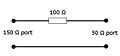 150 ohm to 50 ohm adapter.jpg 391 × 183; 6 KB
 1st screen.png 499 × 387; 13 KB
 2nd screen.png 499 × 387; 21 KB
 3rdScreen.png 499 × 387; 9 KB
 4thScreen.png 499 × 387; 10 KB
 5thScreen.png 499 × 387; 9 KB
 6thScreen.png 499 × 387; 14 KB
 ADChannelInputConfiguration.png 574 × 490; 19 KB
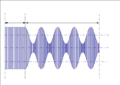 AM Modulated Signal Amplitude Conservation.png 639 × 451; 4 KB
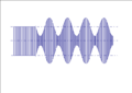 AM Modulated Signal No Conservation.png 639 × 451; 3 KB
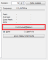 AN101 Continuous Measure Manual Mode.png 295 × 364; 9 KB
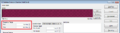 AN101 Frequency Range.png 1,018 × 280; 29 KB
 AN101 Graph Angle overview.png 635 × 90; 6 KB
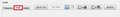
 AN101 No Peaks No Final Detectors.png 346 × 284; 8 KB
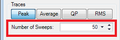 AN101 Number Of Sweeps.png 273 × 90; 4 KB
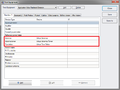
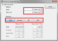 AN101 Optimize Angle Settings TSF.png 481 × 340; 20 KB
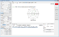
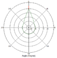 AN101 Polar Plot Angle.png 485 × 491; 13 KB
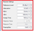 AN101 Receiver Settings.png 272 × 245; 7 KB
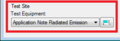 AN101 Test-Site.png 270 × 93; 4 KB
 AN101 Test Equipment.png 775 × 581; 31 KB
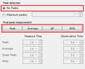
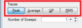 AN101 Traces.png 270 × 93; 5 KB
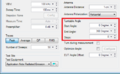 AN101 Turntable Angle.png 528 × 324; 28 KB
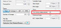 AN101 Turntable Angle Turn during measurement.png 525 × 242; 14 KB
 AN103 AntennaDiagramFinalPolarPlotGraph.png 1,439 × 914; 93 KB
 AN103 AntennaDiagramFrequencyGraph.png 1,439 × 915; 80 KB
 AN103 AntennaDiagramPolarPlotGraph.png 1,439 × 914; 88 KB
 AN103 AntennaDiagramTSF.png 1,035 × 710; 55 KB
 AN103 AntennaDiagramTSFMultipleFrequencies.png 1,035 × 710; 66 KB
 AaroniaSpectran Driver communication.png 510 × 465; 8 KB
 AbsorbingClampOverload.png 890 × 458; 26 KB
 AddCableTestEquipment.png 845 × 474; 20 KB
 AddColumns.png 776 × 375; 15 KB
 AddDriver2.png 1,664 × 820; 84 KB
 AddFieldProbes.png 707 × 400; 11 KB
 AddProbesToTestSite.png 1,680 × 1,050; 88 KB
 AddedProbestoInputs.png 1,210 × 1,006; 86 KB
 AdvancedAntennaTowerPanel.png 498 × 483; 11 KB
 AdvanedSwitchMatrix.png 512 × 463; 12 KB
 AgilentU2000ASettings.png 497 × 464; 9 KB
 Agilent N9038A Input Tab.png 608 × 401; 12 KB
 Agilent N9038A Settings Tab.png 608 × 401; 12 KB
 Amplifier.png 699 × 714; 17 KB
 AmplifierControlWindow.png 469 × 139; 4 KB
 AmplifierControlWindowManager.png 471 × 126; 5 KB
 AmplifierControlWindowOpening.png 911 × 272; 15 KB
 Amplifier control window.png 303 × 294; 5 KB
 Antenna correction factor.png 732 × 765; 28 KB
 Attachments.png 1,022 × 793; 23 KB
 AttenuationGainSystemCalibration.png 960 × 318; 19 KB
 Attenuation EUT Calibration Configuration Window.png 700 × 465; 23 KB
 Attenuation EUT Calibration Result Window.png 748 × 603; 32 KB
 Attenuation System Calibration Configuration Window.png 668 × 478; 21 KB
 AuthorizationTab.png 513 × 436; 6 KB
 AutoPolling.png 1,013 × 553; 42 KB
 AutoResize.png 839 × 761; 26 KB
 AxisSpecificCorrections.png 774 × 372; 16 KB
 BackupDeviceDrivers.png 956 × 470; 34 KB
 Black Dongle.JPG 500 × 142; 25 KB
 Black Dongle Sleutel Hanger.JPG 500 × 277; 40 KB
 CANoeExample.png 1,267 × 1,016; 211 KB
 CANoeSystemVariables.png 685 × 735; 45 KB
 CANoe AD Convertor signal selector.png 439 × 330; 9 KB
 CANoe CAPL messages.png 1,267 × 1,017; 72 KB
 CANoe EUT Monitoring Input Setup.png 604 × 539; 22 KB
 CANoe Simulation setup.png 1,267 × 1,017; 66 KB
 CE101 Test Configuration.png 1,049 × 725; 50 KB
 CE101 Test Result.png 1,286 × 860; 78 KB
 CE101 Test layout.png 923 × 576; 13 KB
 CE102 Test Configuration.png 994 × 725; 51 KB
 CE102 Test Result.png 1,282 × 910; 102 KB
 CE102 Test layout.png 976 × 484; 14 KB
 CS109 Test Configuration.png 1,017 × 693; 39 KB
 CS109 Test Result.png 1,277 × 850; 66 KB
 CS109 Test Setup.png 1,019 × 477; 32 KB
 CS109 Test level.png 1,011 × 507; 30 KB
 CS109 Test level configuration.png 610 × 280; 11 KB
 CS114 Calibration.png 934 × 479; 32 KB
 CS114 Calibration band 1.png 677 × 566; 35 KB
 CS114 Current Testlevel Configuration.png 755 × 420; 22 KB
 CS114 Current limit.png 610 × 280; 10 KB
 CS114 EUT Testing.png 1,126 × 498; 35 KB
 CS114 Equipment 1.png 845 × 474; 21 KB
 CS114 Equipment 2.png 845 × 474; 21 KB
 CS114 Equipment 3.png 845 × 474; 23 KB
 CS114 Modulation settings.png 690 × 370; 14 KB
 CS114 Test Result.png 1,283 × 850; 82 KB
 CS114 Test Setup.png 1,017 × 693; 40 KB
 CS114 Test level.png 1,123 × 557; 41 KB
 CS114 Verification.png 942 × 498; 30 KB
 CS114 Verification Result.png 1,283 × 850; 79 KB
 CS114 Verification Setup.png 1,017 × 693; 41 KB
 CableDeviceDriver.png 730 × 721; 22 KB
 CalibrationExpireDatabase.png 946 × 536; 9 KB
 Calibration jig factor 0 dB for 50 Ohm system.png 366 × 210; 9 KB
 Calibration jig factor 150 Ohm for 150 Ohm system.png 366 × 199; 8 KB


